


Jharkhand
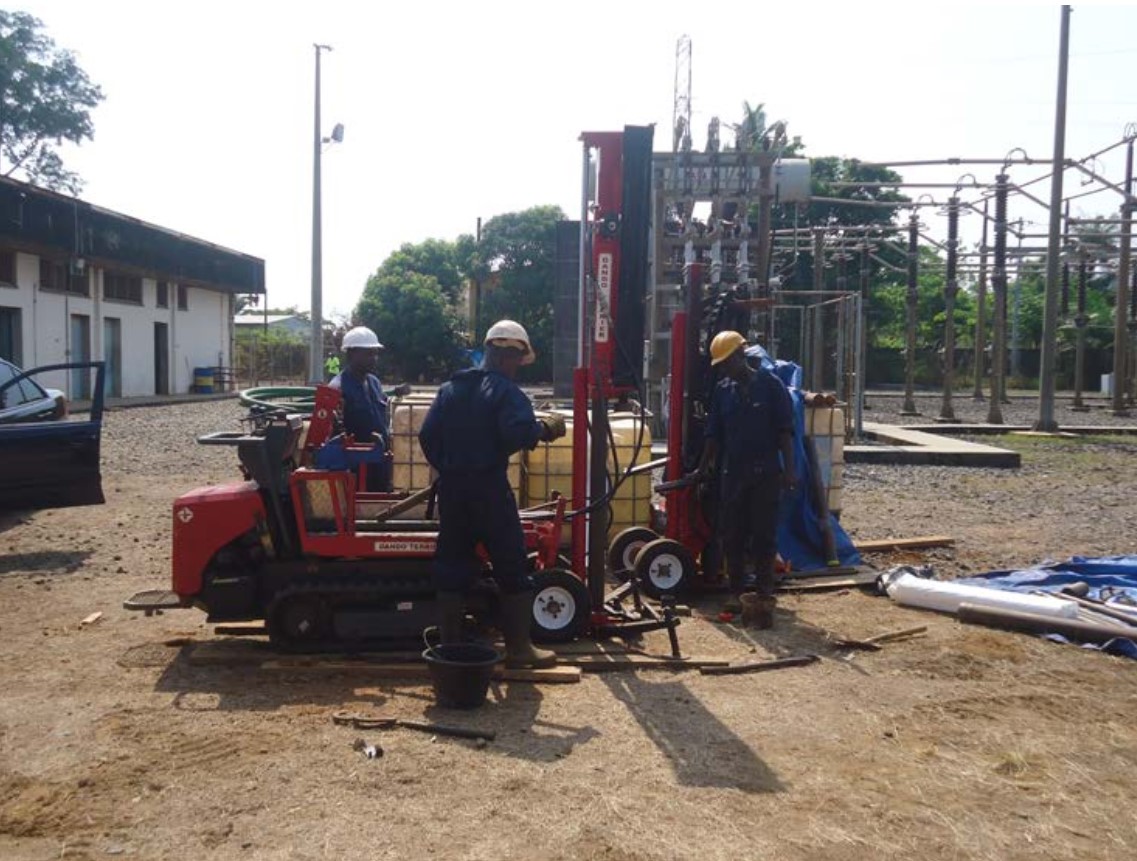
Pile Foundation of all types of 220KV Multi...


Scope of Work :
| SL. NO. | DESCRIPTION |
| A. | ELECTRICAL DRAWINGS : |
| 1 | SLD |
| 1.1 | Key SLD - 220 KV Substation (02 Nos Line Bays) |
| 1.2 | Protection and Metering SLD - 220 KV Substation (02 Nos Line Bays) |
| 1.3 | SLD - 415V AC Distribution |
| 1.4 | SLD - 250V & 48V DC Distribution |
| 2 | ELECTRICAL LAYOUT & ELEVATION, EKD |
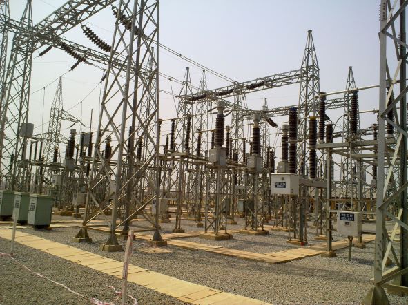
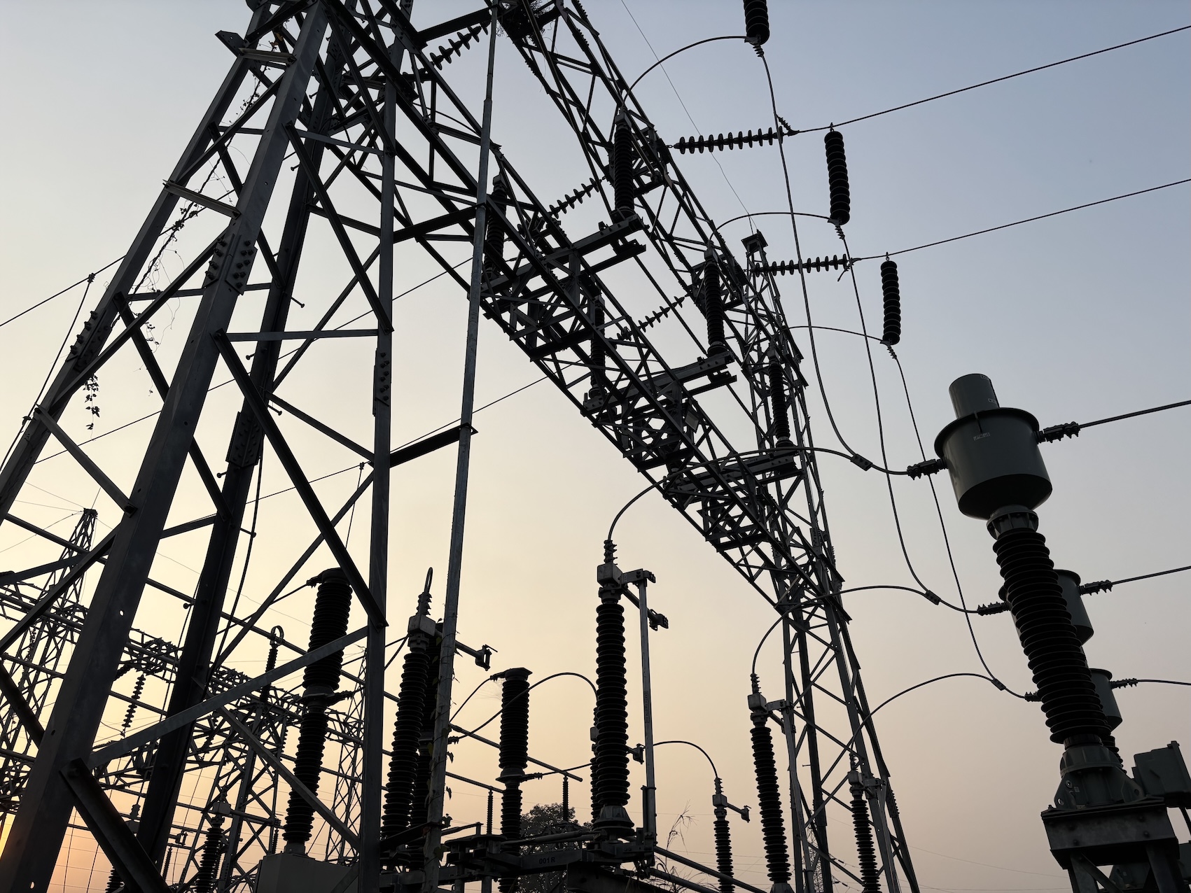
| 2.1 | 220 kV Switchyard Layout (02 Nos Line Bays)- Plan & Elevation |
| 2.2 | Erection key diagram of 220 kV Switchyard (02 Nos Line Bays) - Plan & Elevation |
| 2.3 | Electrical Equipment Layout with cable trench details - Control Building. |
| 3 | CABLE ROUTING, TRAY & TRENCH LAYOUT AND DETAILS |
| 3.1 | 220/132/33kV Switchyard - Cable trench layout and sections with BOM of cable trays |
| 4 | EARTHING LAYOUT & DETAILS |
| 4.1 | 220 KV Switchyard (02 Nos Line Bays) - Earthing layout & BOM |
| 5 | ILLUMINATION AND SMALL POWER LAYOUT |
| 5.1 | 220kV Switchyard (02 Nos Line Bays) - Illumination layout, SLD and BOM |
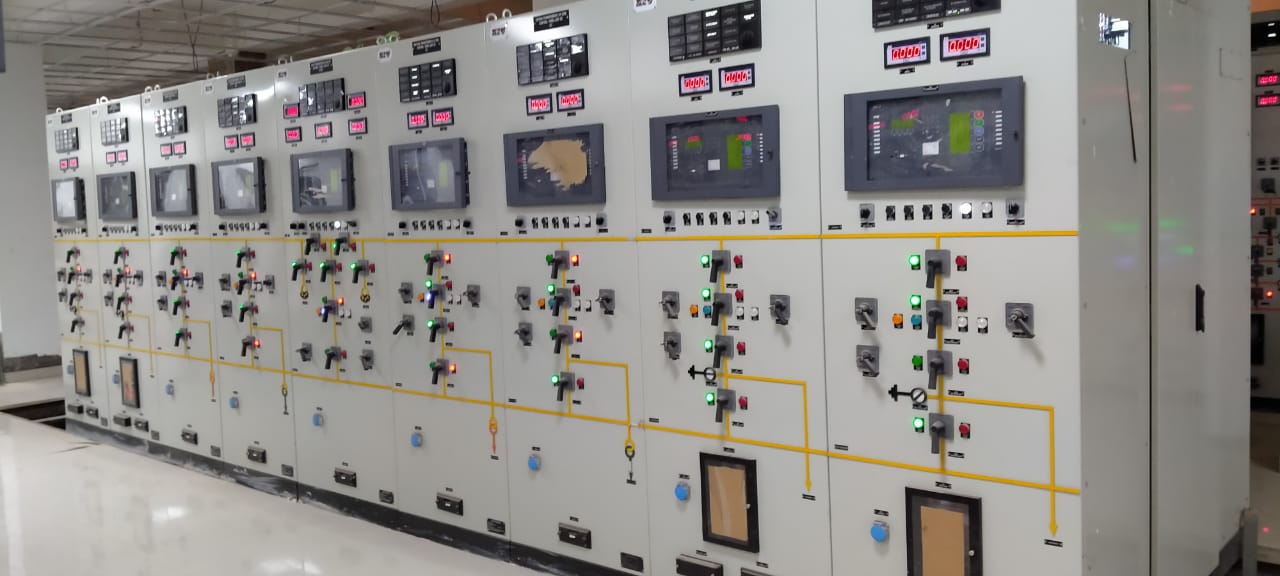
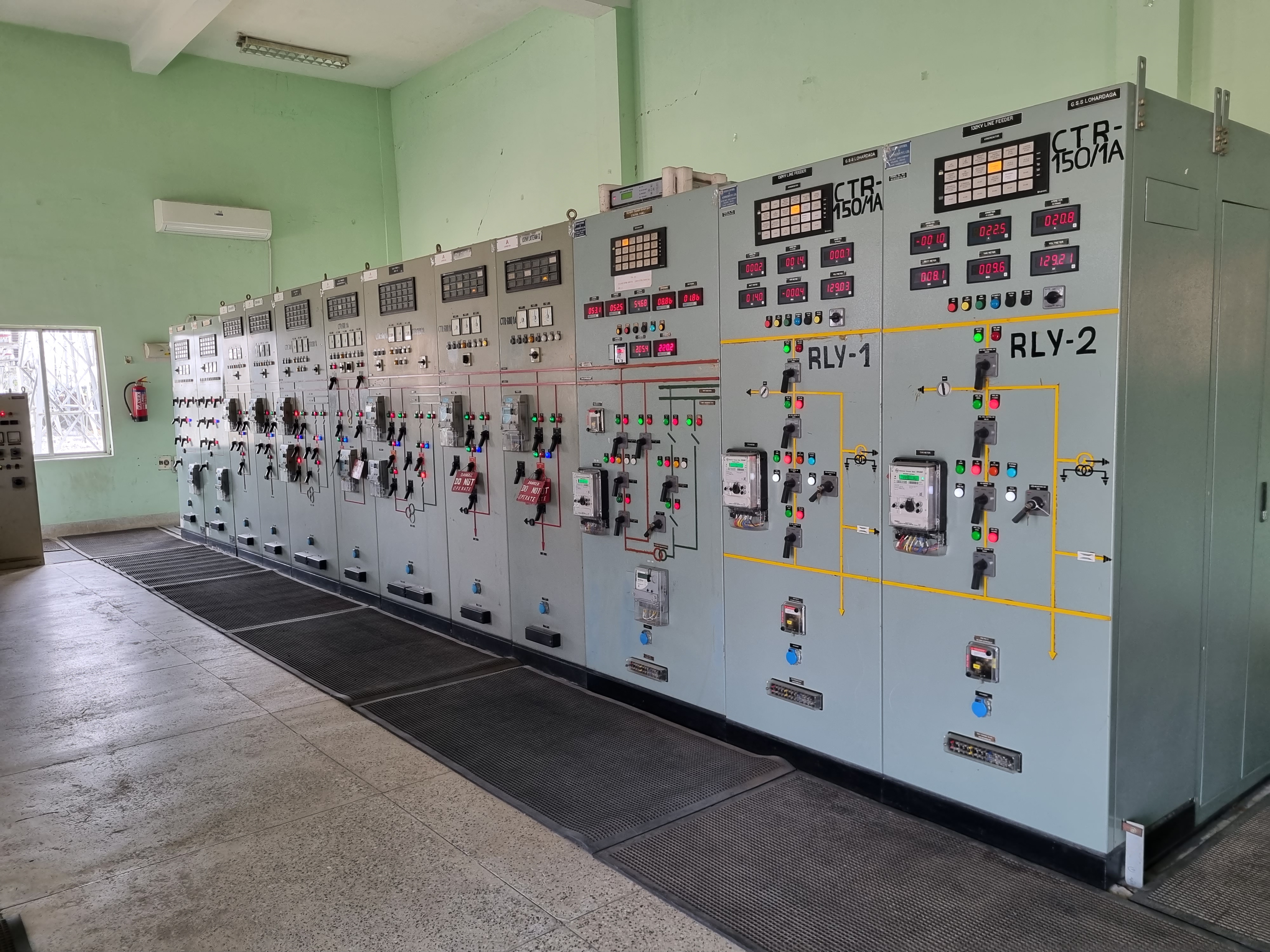
| 6 | CONTROL SCHEMATICS & BLOCK DIAGRAMS |
| 6.1 | 220KV Intelocking Logic Diagram at BMK |
| 7 | CABLE SCHEDULE & INTERCONNECTION DIAGRAMS |
| 7.1 | 220kV Switchyard - Control Cable schedule and Interconnection Diagrams |
| 7.2 | ACDB, DCDB, LDBs, BMK - Power Cable Schedule and Interconnection Diagram |
| 8 | SCADA |
| 8.1 | SCADA Block diagram for 220kV system |
| B | ELECTRICAL DESIGN CALCULATIONS |
| 1 | 220kV Switchyard (02 Nos Line Bays) - Earthing calculation |
| 2 | 220V DC Battery Sizing Calculation (Adequacy Checking) |
| 3 | 220V DC Battery Charger Sizing Calculation (Adequacy Checking) |
| 4 | Lighting calculation - 220kV Switchyard (02 Nos Line Bays) |
| 5 | Short Circuit Force Calculation for strung bus |
| 6 | Sag & Tension Calculation of strung bus conductor |
| C | STRUCTURAL DRAWINGS WITH BOM AND WEIGHT AND DESIGN CALCULATIONS |
| 1 | Overall structural layout of 220kV switchyard (02 Nos Line Bays) - Plan & Elevation |
| C.1 | STRUCTURAL DRAWING : FOR 220KV TOWER & EQUIPMENT |
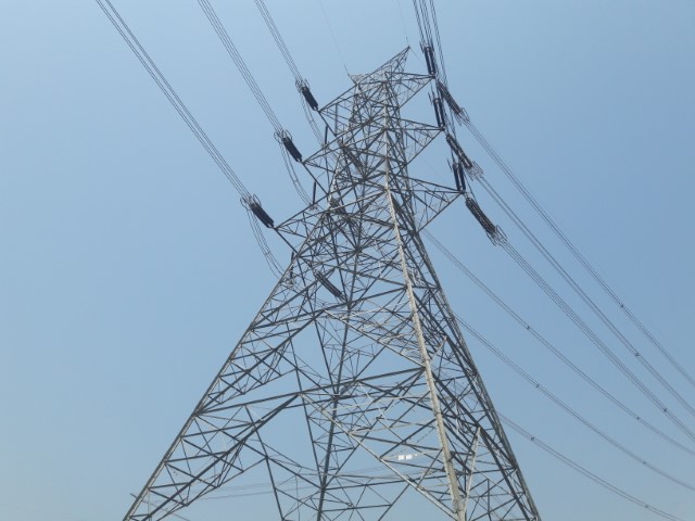
| 1 | GA drawing of 220kV Line gantry tower |
| 2 | GA drawing of 220kV Line gantry beam |
| 3 | GA drawing of 220kV Main bus tower |
| 4 | GA drawing of 220kV Main bus beam |
| 5 | GA drawing of 220kV Transfer bus tower |
| 6 | GA drawing of 220kV Transfer bus beam |
| 7 | GA drawing of support structure for 220kV Isolator with E/S |
| 8 | GA drawing of support structure for 220kV Isolator without E/S |
| 9 | GA drawing of support structure for 220kV LA |
| 10 | GA drawing of support structure for 220kV CVT |
| 11 | GA drawing of support structure for 220kV WT |
| 12 | GA drawing of support structure for 220kV CT |
| 13 | GA drawing of support structure for 220kV BPI |
| C.2 | STRUCTURAL DESIGN CALCULATIONS : |
| 1 | Structural design calculations - 220kV |
| D | CIVIL CONSTRUCTIONAL DRAWINGS AND DESIGN CALCULATIONS |
| 1 | Overall foundation layout of 220kV switchyard (02 Nos Line Bays) |
| D.1 | 220KV GANTRY TOWER AND EQUIPMENT FOUNDATION DETAILS: |
| 1 | Foundation details of 220kV Line gantry tower |
| 2 | Foundation details of 220kV Main bus tower |
| 3 | Foundation details of 220kV Transfer bus tower |
| 4 | Foundation details of support structure for 220kV Isolator with earth switch |
| 5 | Foundation details of support structure for 220kV Isolator without earth switch |
| 6 | Foundation details of support structure for 220kV LA |
| 7 | Foundation details of support structure for 220kV CVT |
| 8 | Foundation details of support structure for 220kV WT |
| 9 | Foundation details of support structure for 220kV CT |
| 10 | Foundation details of support structure for 220kV BPI |
| 11 | Foundation details of support structure for 220kV CB |
| 12 | Foundation design calculations by Staad software |
| D.2 | OTHER CIVIL CONSTRUCTIONAL DETAILS AND DESIGN CALCULATIONS |
| 1 | Outdoor cable trench and trench cover slab |
| 2 | Surface water drainage layout |
| D.3 | MISC. CIVIL DESIGN CALCULATIONS |
| 1 | Design calculation for outdoor cable trench |
| 2 | Design calculation for surface water drainage system |
| E | ADDITIONAL |
| 1 | Vendor drawing review and approval |
| 2 | As built drawings |