


Jharkhand
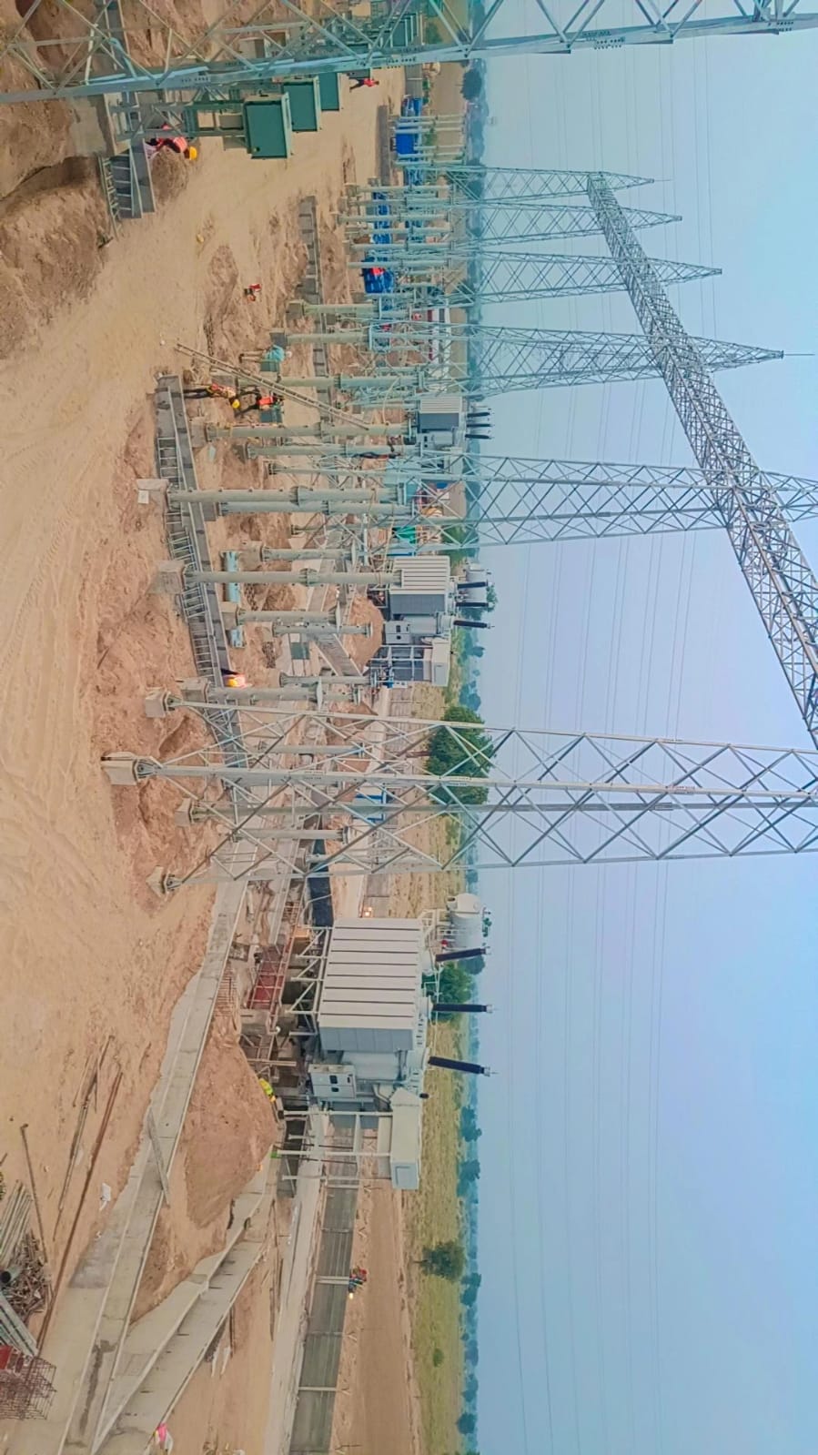
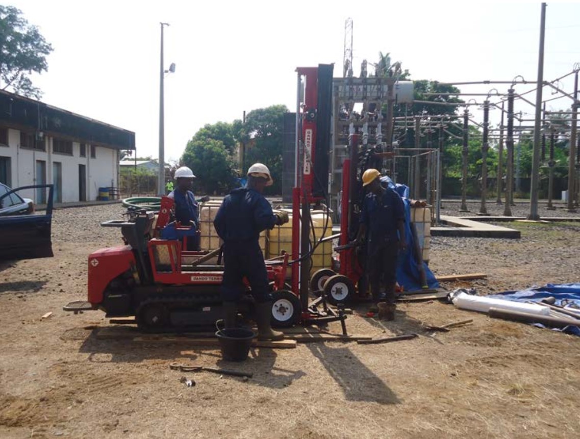
Pile Foundation of all types of 220KV Multi...

1. Design detailing of Isolator, Insulators & allied structure at 33 KV Port Switchyard.
a. Single line diagram mentioning the rating of equipment and method of tapping from existing switchyard.
b. Layout plan & elevation of 33kV Bay modification.
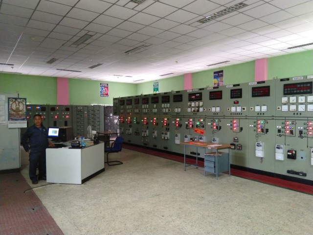
c. Electrical layout of existing control building showing the location of new panels.
d. Structural GA drawing and design calculation of support structures of 33kV Isolator, CT, PT, LA, PI and Cable termination.
e. Foundation drawing and design calculation of 33kV Isolator, CT, PT, LA, PI, Cable termination and VCB.
2. Selection of Lightening Arrestor, CT & PT at 33 KV Port Switchyard.
a. The ratings will be shown in sl. 1.a above.
3. Selection of 33 KV VCB and necessary protection system.
a. Protection and metering SLD of the 33kV Bay.
b. Specification of 33kV VCB.
4. Drawing development of cable supporting structure.
a. Included in 1.d & e above.
5. 33 KV Cable specification and length with jointing kit.
6. SLD, Electrical Layout and Cable trench layout of 33/6.6kV Temporary substation.
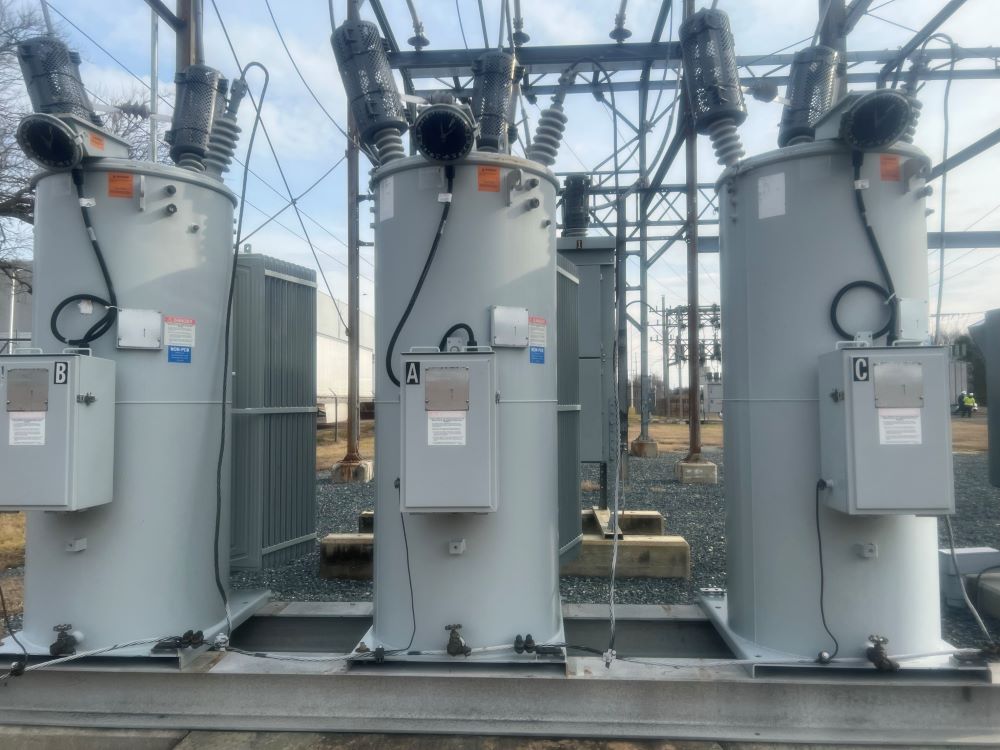
7. Detailed specification of 33kV/6.6 kV, 6 MVA Transformer.
- It is excluded from scope since the main consultant has already provided the spec.
8. Specification of 6.6kV grade cable with end termination kit.
9. Specification of 6.6kV/433 volts 1250 KVA Transformer.
10. Specification of 6.6kV/433 volts unitized portable sub-station
11. Earthing system.
a. Earthing system design calculation, layout and BOQ for 33kV bay at Port Switchyard.
b. Earthing system design calculation, layout and BOQ for 33/6.6kV Temporary substation.
12. Battery and Battery Charger.
a. Battery and Battery charger sizing calculations for 33/6.6kV Temporary substation and 33kV bay extension at Port Substation.
13. Power Factor correction equipment.
a. APFC sizing calculation, SLD and Technical specification.
14. 1.1 kV grade power and control cables.
a. LV Power and control cable schedule and interconnection chart for 33kV bay at Port switchyard.
b. LV Power and control cable schedule and interconnection chart for 33/6.6kV Temporary substation.
c. Technical specification of LV Power and Control cables.
15. DCDB, MLDB , Lighting of Berth area and sub station area
a. SLD of 110V DCDB.
b. SLD of 415V Main Lighting Dist. Board (MLDB).
c. Lighting layout, SLD and BOQ of Berth area.
d. Lighting calculation of Berth area.
e. Lighting layout, SLD and BOQ of 33/6.6kV Temporary substation.
f. Lighting calculation of 33/6.6kV Temporary substation.
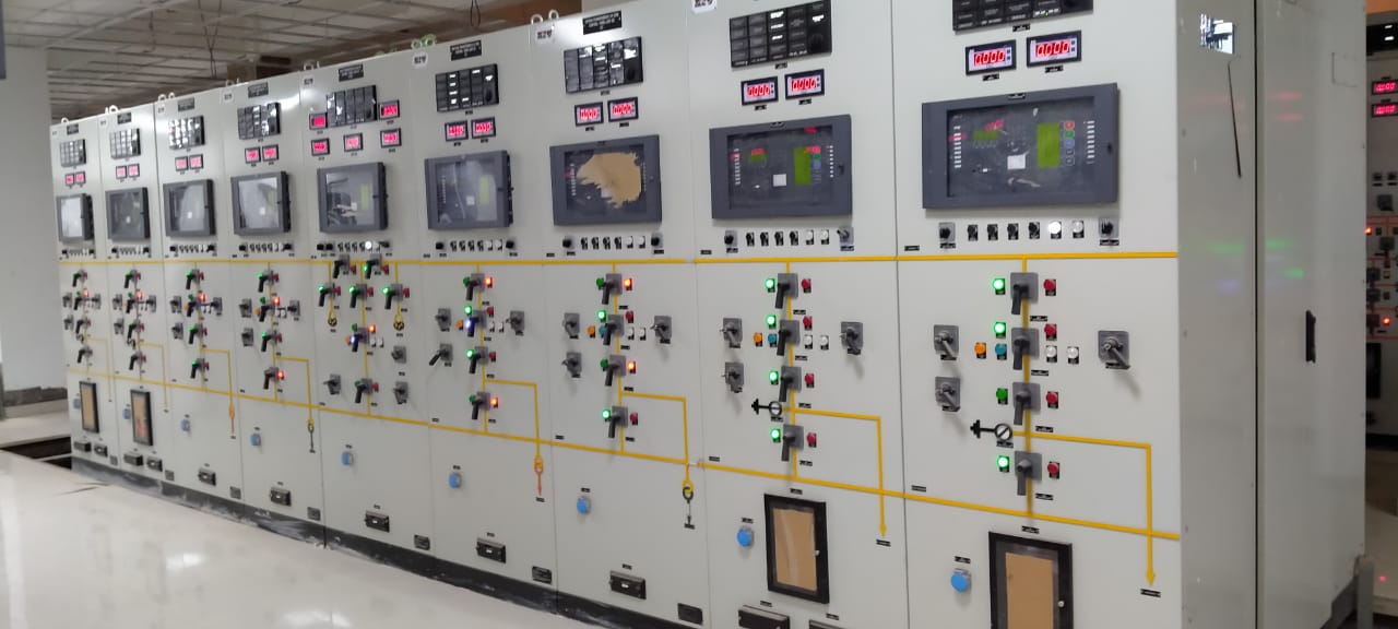
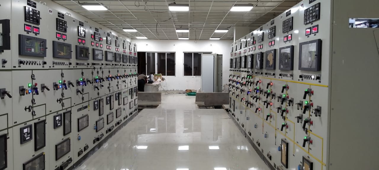
16. Control Panels.
a. Technical specification of the 33kV Control and Relay panel at Port Switchyard.
17. Welding distribution board equipments at berth area.
a. SLD and Technical specification of Welding dist. Board for Berth area.
18. Contractors’ scope of work and BOQ
a. Preparation of detail BOQ of Electrical, civil and structural work for installation of 33kV Bay at Port switchyard, 33/6.6kV Temporary Substation.
b. Technical specification of Erection, Testing, Commissioning, Civil and Structural works of 33kV Bay at Port switchyard, 33/6.6kV Temporary Substation.
19. Vendor drawings review and approval of the following bought out items :
20. Preparation of Civil and structural drawings for temporary substatio
Our scope shall include the following under this item :